|
|
|
Cylinder Head and Valves At the heart of every powerful engine you will always find one thing; A good cylinder head. For an engine to work, it needs to be supplied with two things, fuel and air. Fuel is easy to supply in large quantities because you can just pump it in faster. But there is no point in filling the cylinder full of fuel, because without air, it wont burn. In fact even with air, unless the ratio of air to fuel is within a certain range, it still wont burn very well. So if it is easy to put lots of fuel into the cylinder, why don't we just put loads of air in to match it? Well, effectively that is exactly what we want to do, and we can to a certain degree achieve that in various ways. We can either push air in or pull air in. But there are limitations to what we can do.
Forced Induction
Two of the most common ways of pushing air into an engine are turbo- and super-charging. They each achieve the same goal, in a similar way. Both use an air pump to induce and compress air, which is then forced under pressure into the cylinder. The turbo charger normally uses a centrifugal impeller, similar in design to the compressors found in helicopter gas turbine engines. This is driven by a turbine, which is in turn driven by the exhaust gases from the cylinders it is pumping air into. The advantages of these is that they can achieve a high compression ratio for a single stage, and that if you double the rotational speed of the compressor, you can pump four times the amount of air. The turbo is de-coupled from the engine, therefore uses no engine power, just what would be waste energy. It can quieten an engines exhaust very considerably. The disadvantages are that they have to spin very quickly to produce the necessary pumping effect, and run very hot due to the exhaust gases impinging on the turbine, so they are relatively fragile. They heat up the incoming air to a very high temperature, reducing its density and increasing the likelihood of detonation. They are slow to spin up from low speeds, creating a lag between throttle application and the delivery of the power. At high delivery rates, they raise the effective compression ratio of the engine, increasing the likelihood of detonation, so the engine compression ratio is lowered to compensate, but when the engine is at low speeds (off boost), this lowered compression ratio causes low power. They require a blow off valve to protect the engine from over-boosting. A supercharger is engine driven, and the compressor can be an impeller, as in the turbo, but more often is either a Rootes type rotor or a screw type rotor, both of which function better at lower speeds than the impeller. The supercharger works lower down in the rev range, boosting torque, so there is no lag as in the turbo, It tends to run out of puff at the higher end though, and as engine speeds increase the power required to drive it increases too. Another less common method of pushing air, or more correctly oxygen, into the cylinder is to use nitrous oxide injection. This can be sprayed into the engine just like fuel, and with the fuel, and the oxygen released will burn with the fuel, giving a significant jump in power. This tends to be a bit crude, and is more suited to short bursts of use like drag racing, as it creates tremendous amounts of heat. All these methods work, and with some of the better installations provide fantastic performance from a modest engine capacity. The trouble is that for a home tuner, they are too complicated and problematic. Which leaves pulling more air in.
Normally aspirated engines
The pistons in the cylinders of any engine function like pumps for half of the time. After the piston has been pushed down by the burning gases of the power stroke, it then turns round and starts back up the bore. At this point, the exhaust valve opens, and the piston then pushes all those burnt gases past the valve and into the exhaust. As it reaches the top of the cylinder, the inlet valve opens and the exhaust valve closes. The piston is then pulled back down the bore by the power stroke of one of the adjacent cylinders, and in going down creates a vacuum behind it. This vacuum then pulls air past the inlet valve into the cylinder. This air carries the fuel suspended in it that will then be compressed and then ignited. The problem comes when you consider that the piston is say 84mm in diameter, and it displaces more or less 375cc. That 375cc of air that is required all has to get past the open valve by the time that the valve has closed. This means that as the inlet valve is open for only one half a crankshaft revolution, at 6000 rpm, the air has 1/200th of a second in which to fill the cylinder. Air is not weightless (actually, massless is the more correct term), and this mass needs time to accelerate up to the speed necessary to flow past the valves. The valve is a fraction of the diameter of the piston, and some of its time is spent opening and closing, so it is not fully open for much of the time. In addition, before it got to the valve, the air had to pass though a filter, then the carburettor or injection throttle body, then the intake manifold and then the inlet port in the head. All these items offer restrictions to the flow of air. So the net effect of this is that the quantity of air that actually gets into the cylinder is normally considerably less that the theoretical maximum possible. It gets more complicated still when you consider that once you have burned the mixture you did manage to induce, the resultant gases have to be pushed out past another valve that is even smaller that the one you just pulled the mix in through. If the exhaust valve offers any resistance to the gases being pushed out, clearly you are not going to get it all out in the 1/200th of a second you have available. This means that when you start to pull the piston down the bore, you still have some positive pressure, which has to reduce to negative pressure before you start to pull anything in. The positive pressure also can push gases past the inlet valve which has now obligingly opened, so the first lot of 'inlet charge' that will be pulled in will in fact be exhaust gases. All this conspires to make it so that if your cylinder has a capacity of 375 cc, the actual amount of combustible charge that you get in the cylinder is maybe 187.5cc, which represents a 50% volumetric efficiency. It means that you can at the maximum produce 50% of the power that you can theoretically get. In addition to this, because of the fact that when the inlet valve closed, there was still negative pressure in the cylinder, maybe 75% of ambient. That means when you start to compress the mix, the effective compression ratio will only be 75% of the engines possible compression ratio. Compression ratio directly relates to power by increasing the pressure on the piston, so a drop in compression means lost power. So what can be be done to improve this situation? We can do any of the following: Increase the inlet valve size Increase the time that the inlet valve is open Open the inlet valve faster Increase the exhaust valve size Increase the time the exhaust valve is open Open the exhaust valve faster Decrease the restrictions in the inlet and exhaust ports Decrease the restrictions in the inlet manifold and exhaust system Decrease the restrictions caused by the filter, fuel injection throttle body or carburettor and associated equipment. You can see that the majority of these improvements fall within the area of the head. But before we move on to modifications, there are other effects which come into play that will affect how we modify things.
Camshafts
The cams function is actually simple, but the effect it has on the engine is anything but, having some far reaching consequences. It's primary function is to open and close the inlet and exhaust valves to the correct height at the correct time in the correct sequence, and then return them to the closed position, all without losing control over their movement. It is their secondary functions, better described as effects, which complicates matters. The cams deal with increasing power by addressing some of the requirements stated above, namely opening and closing the valves further, longer or faster, and any combination of these. If the valves don't flow much gas or air when they are just opening or closing we can open them earlier and close them later with not much loss. By holding the valves open for longer, the cam can give the air more time to get in and the exhaust more time to get out. The exhaust valve can start to open early so that when the piston is starting to push the exhaust out, the valve is fully opened, and start to close when the gases are almost completely out. The same can happen with the inlet valve. Taking this to it's logical conclusion, it can be seen that to make the best out of the valves, there comes a point where the exhaust valve is still closing, and at the same time the inlet valve is opening. This is known as valve overlap. This creates an effect, depending on the amount of overlap, that can be beneficial. It can also be very detrimental if not understood. What happens is that, as discussed, air, gas, exhaust etc all have inertia. This works both in trying to accelerate the gases as well as trying top stop it. When the exhaust valve opens, the residual pressure inside the cylinder starts pushing the exhaust gas out, then the piston joins in and helps keep a nice flow of gas through the port and into the exhaust. With the high speed comes inertia, and at high rpm and therefore gas speed, that inertia is so high that the gas doesn't want to stop. So if you leave the exhaust valve open for a bit longer, the plug of gases rushing down the exhaust starts to leave a vacuum behind it, and keeps pulling the exhaust gases out of the cylinder after the piston has stopped pushing it. In this way, it is possible for the residual pressure in the cylinder to be nice and low when the inlet valve opens, so there is no positive pressure pushing the inlet charge out. In fact, if you leave the exhaust valve open for longer still, the exhaust gas actually starts to create a vacuum in the cylinder before the piston starts moving down the bore. If the inlet valve is open at the same time, the inlet charge starts to be pulled in before the piston starts moving, which means that the amount of inlet charge pulled in by the piston is in addition to the 'free' extra provided by the exhaust. This effect is really a form of pulse tuning. So what we need to do is make sure that the overlap is quite long to ensure we get power, right? Well, there is no such thing as a free lunch. That effect works wonderfully once the engine has got up to a certain rpm, and the gas speeds are high enough. The point at which this starts to work is the point that the engine come up onto the cam. Below this is a sadder story. At low speeds, the gas speeds are not high enough to get this inertia tuning benefit. In fact, exactly the opposite happens. The exhaust gas tries to exit through the exhaust valve and the inlet valve, so the inlet tract is full of exhaust gas, and the cylinder filling is appalling at low speeds. The resultant crappy mix in the cylinder is so difficult to ignite, with so little that is burnable, that no real power is produced. This is the off cam effect. The point at which an engine comes on to the cam varies with a few things. The first is obviously the degree of overlap, and the overall timing of the cam. But in addition to this, the following can have an effect; inlet and exhaust port size; exhaust port shape; carburettor size; exhaust manifold and system back pressure; quality of fuel metering and distribution; compression ratio; cubic capacity of the engine. Camshafts are, along with carburettors, the most mis-used and mis understood items in a modified engine. They can turn a torquey, reasonably powerful smooth engine into a gutless, rough, untractable pig of an engine. Following the principle that more is better, then even more is even better, many engines have been fitted with a cam that is so unsuited to the engine standard and use that it renders the engine unusable for daily use. The plain fact is that you should use the mildest cam you can that suits your application. What tends to happen is that people choose a race/rally cam that has tons of overlap and lift. These are designed to be used in competition, where rpm is kept in the last 25% of the rev range, and traffic lights are not often encountered. These cams are fantastic at high rpm and dogs at low rpm. They then have a car that is undriveable. The 'fast road' cams offered by companies like Piper and Kent are indeed fast road cams. They bring you the benefits of the inertial tuning, without making the engine undriveable. Listen to their advice! The only caveat to this is that the larger the engine cubic capacity, the milder a cam will seem for any given profile. In other words, a rally cam for a 1300cc would be a fast road/rally cam for a 1500cc and a fast road cam for a 1700cc.
High Lift Cams
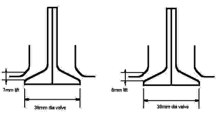
Of course, averyone has heard of the legendary 'high lift' cams. As their name suggests, they aim to improve the engine power by increasing the distance the valve is lifted from the valve seat. The idea is to increase the area through which the air has to pass by opening the valve more. As the area is dependant on the valve diameter multiplied by the amount of lift, the curtain area, as its called, can easily be calculated.
The difference in area made by 1mm extra valve lift Doing the sums, we get for the 7mm valve lift case, 38mm X pi X 7mm lift = 835.66 sq mm On the 8mm lift, we get 38mm X pi X 8mm = 955.04 sq mm As you can see from this, 1mm more lift made over 14% extra valve area. As the area the air has to pass though on its way to the cylinder has a direct effect on how restrictive it is, if we increase the lift, there will be more flow as we have increased the open area for a given valve size. What's more, the valve timing regarding overlap has not changed. This seems very straightforward, and there can't be anything wrong with that principle, right? Well, life's a bitch sometimes, because even this is not as simple as it would seem. In some cases you can actually gain flow and therefore power, as this is effective. But in certain cases, the extra power does not materialise, and in fact in the worst possible case you end up with a lot less power than you started with. If we start with the pitfalls, we can at least look at what to avoid. The worst case scenario is that the lift of your cam is so much that the valve hits the piston. This simply wrecks the engine, so it won't work. It is something that people who have skimmed the head and or block must look closely at, as the valve to piston clearance has already been reduced. That extra millimetre of lift may result in the valve being very close to, if not touching, the piston crown. At high RPM (and remember that power always happens at high RPM for small engines) the con rod stretches slightly, and the piston can hit the valve even though when you measured it statically, there was clearance. When building the engine, try and aim for 2mm piston to valve clearance at the worst point (put some modelling clay on the end of the valve and turn the engine over - the thickness of the clay after this is your clearance). Other problems can occur due to the fact that in the same space of time, you are opening the valve further, so the acceleration applied to the valve must be higher. This increases the stresses borne by all the components, and so if you are fitting a high lift cam to an old or worn engine, the used components may not be able to withstand the wear and loads. As a result, the tappets may wear, causing them to increase the tappet clearance, reducing lift and increasing the rate of wear and noise. The valve springs are also asked to control the valve at higher speeds, and greater levels of compression. The springs may not be able to maintain full control, causing valve float, or bounce, or in the worst cases surging. The lift may be so much that the springs actually get to the point where they cannot compress any further, and effectively become solid - known as spring bind. This would smash the nose of the cam to pieces in short order. Another point to note is that high lift cams use extra power to lift the valves higher and faster, some of the gains in power may be offset by increased mechanical losses. Thankfully, in the case of the Alfa Boxer, the heads are supplied with twin concentric springs per valve, which is a good setup with some performance in hand. Unless you are choosing a really wild cam, the standard setup should be ok, but obviously make sure that all the parts are in good condition. Check that the free lengths of the springs are all more or less equal, and that none of the springs are noticably softer that the others before you put in that cam. The tappets also deserve a good looking at, to make sure that they are not excessively worn, or scored, both on the cam contact face and the diameter that sits in the cam carrier bores. Some notes regarding cam changes. The wildest cams fitted to the 8v boxer engines were those fitted to the 105bhp AlfaSud Green Cloverleaf engines. A higher lift or longer duration camshaft will require a compression ratio increase in order to get the best out of it. Refer to the engine block section for more information regarding how to achieve this. If you fit a higher lift or reprofiled cam, the probability is that either the cam carriers will require machining or you will have to add some spacing shims to the valves to compensate for a smaller cam lobe base circle diameter.
Big Valves
Big valves are very often quoted as being essential, and in fact there are few drawbacks associated with big valves. By far the biggest drawback is cost. But if you can afford them, big valves offer good rewards. By increasing the effective area through which the inlet charge must pass, you reduce one of the sources of restriction to the incoming airflow. Of course, too big a valve can mean a loss in some low down torque due to low airspeed at the valve throat, plus some problems with valve shrouding. The later 1700cc Alfa 33 cylinder heads where produced with valves 1mm larger than previous versions, so if you can source the heads from one of these engines you will gain from this. However, refer to the '16v engines versus big valves' section at the foot of the page for more details on big valves. Whether or not you are able to get hold of the bigger valve heads, there are some modifications that can be performed to the valves that will aid the passage of air into the cylinder, and help get the exhaust out of the cylinder.
Inlet valve
Taking the inlet valve in isolation, the following can be done. The traditional valve head is like a tulip shape, but as the Boxer does not have a combustion chamber as such in the head, this is not the best arrangement. What works better is to have a 'penny on a stick' type valve. So, referring to the diagram, the back of the head can be cut back considerably in order to achieve this. When doing so, make sure that all radii are smooth, and that the radius between the stem and the head is generous. If it is too sharp it becomes a stress raiser point, and may cause the head to break off. The stem itself also offers some resistance to flow, being a fairly beefy diameter. By thinning the portion of the valve stem that protrudes into the port WITH THE VALVE CLOSED by 1.5mm, you can improve this. If you thin the stem where it fits into the valve guide, the effective bearing length of the valve guide is reduced, and accelerated wear will take place. The valve may eventually rock in its guide, causing poor sealing of the valve. As before, make sure that there is a generous radius between the stem and the head. When the air is passing over the back of the head into the cylinder, it has to turn sharply to go around the edge of the head. Air doesn't like turning sharply, and it causes turbulence which resists the passage of air. To aid this, the head is radiused to meet the valve seat. The valve seat cannot be curved, as it needs a conical seating of a minimum width to match the head. To match the back of the valve to the seat, an additional angled cutback is used, and then one more used directly after the seat. This set of angles constitutes the 3 angle seat arrangement in the diagram. This progressively turns the air. A matching three angle seat is used on the valve seat in the cylinder head. If you look back through the text, you will see that sometimes, at low rpm, exhaust gases flow out of the inlet valve. This is due to the unfortunate fact that these poppet type valves function better as exhaust valves than as inlet valves. This reversal of flow is what contributes to the poor running off the cam. A modification that can be performed is to introduce an anti-reversion groove. The anti reversion groove acts to make the inlet valve less attractive to the exhaust gases as a means to escape from the cylinder. As the gases flow over the face of the valve, the groove disrupts the flow, and discourages the gas from exiting so easily. The increased volume of gases going out of the exhaust valve has a higher speed, and therefore the inertial tuning starts earlier in the rev range. If you decide to do this mod, make sure that you leave at least 2.5 mm between the edge of the groove and the rim of the valve to prevent hot spots. The edge of the valve between the face and the rim of the valve is also best left sharp. One final thing to consider. Valves get hot, due to the effect of the combustion occurring directly against the largest part of the valve. As the intake charge comes in, it cools the valve, but in doing so it heats up the air. Hot air is less dense, therefore contains less mass of air for a given volume. This means less power. In addition, hot inlet charges are more prone to detonation. What we want to do is prevent the valve picking up the heat, so that the intake charge is not heated. This can be done using thermal barrier coatings, such as ceramics. If you look at the photos of my modified inlet valves, you will see a white coating on the faces. This is a partially yttria stabilised zirconium ceramic coating which has been applied with a process called plasma spray. I got this done for free because I work in the aircraft engine industry, where these coating are extensively used in engine combustion chambers and turbine nozzle guide vanes. However, there are an increasing number of places that offer this type of service. Whether or not the coating actually made any significant difference to my engine is unclear. The problem is that it was put in the engine at the same time as a number of other mods, and its individual contribution to the increase in power is unknown. As a result of this, I cannot say what the value of this mod is, and if you had to pay for it it may be expensive. The engine will certainly run ok without it!
Inlet valve mods Exhaust valve The exhaust valve is somewhat easier to modify. As mentioned, these type of valves actually function quite well in the form of exhaust valves. The main things to remember are that if you remove too much material from the valve head, the hot exhaust gases passing over it will overheat the valve head, and that if you make the valve seat too thin, the transfer of heat away from the valve is affected. The best form for the valve is to have a smooth change in profile all the way from the face to the stem, and to be polished to offer as little resistance as possible. A three angle valve seat with a minimum seat width has to be included, but all else is there to blend them all smoothly together.
Exhaust valve mods Inlet ports This is the subject of many urban legends and mistaken practices which fall under the catch all title of 'porting'. A properly prepared cylinder head has an inlet port which is modified in very specific ways in order to suit a specific task. A full race cylinder head is modified very differently to a fast road one, to take advantage of the different requirements. Very often it is believed that hacking lots of metal out of the inlet port to make it as big as possible will make the engine produce a lot of power. Unfortunately, unless the cam is correct, and the engine is revved to very high rpm, plus the fuel system and exhaust system is matched to suit, those extra bhp do not materialise. In fact, at low speeds, just as with too wild a cam, a substantial amount of power is lost. The aim is to get as much air as possible into the cylinder, as has been said before. At high rpm, the amount of air rushing through the port is significant, and so the air speed is high. But you have to consider what is the practical limiter to the amount of air going into the cylinder. In most cases it is actually the valve and throat of the port. If this area is too small, or too restrictive, opening up the rest of the port will not help. In fact, at low rpm, a big port means that the air may actually be travelling too slowly. When that happens, a couple of things can happen. The first is that the slow air allows the fuel to drop out of the airstream, and condense on the walls of the port. this means that you do not have a readily combustible mix entering the cylinder. As the air is not travelling quickly, it is easier for the exhaust gas to push it back up the inlet port, contaminating the inlet charge. So what is needed is the smallest port that easily flows the amount of air that the valve and throat can accept. It can also be seen that if you want to improve things, you have to start with the most restrictive areas of the head, the valve throat. By blending the valve throat area to ensure the smoothest transition, you achieve the most effect for the least work. You are looking to open out this area to best match to the valve seat, but no further. Beyond this, the short side radius can be blended to achieve the best change in profile as per the diagram, so that the air has a smoother turn to navigate. Finish the valve seat by producing a good three angle valve seat. The rest of the port must not be made any bigger, otherwise the low speed flow will suffer. Just make sure that that are no big casting lumps or sharp edges that would provide excess resistance, especially on the port roof. During high speed running, the air will be biased to the outside of the turn of the port, which is the roof, and so the general profile has to be smooth. The valve guide is located in this area, so blending the valve guide boss to improve flow around it is worthwhile, as long as you don't make the port bigger. A common misconception is that highly polishing the ports will make the ports flow better. It might make 0.2% improvement to the flow at high rpm, but at low rpm it actually is a disadvantage. A rough surface finish to the port walls acts as a good way to reintroduce fuel that has dropped out of the airstream back into it. The greater surface area allows the fuel to be heated more, and the roughness produces a boundary layer or turbulence that helps evaporate the fuel and mix it with the air. At low speeds, this compensates for the low airspeed, making the intake charge burn better. This results in better low speed power. The effect of the rough surface on air speed at high rpm is negligible. Finish the inside of the port with 80 grit abrasive paper. The inlet manifold can also be considered with this, and really is part of the port. As per the port, all you want is the smallest diameter necessary to flow the air. If the carburettor is a 36mm diameter bore, then quite obviously the entrance to the manifold also has to be 36mm. After this, it can taper smoothly down to the diameter of the entrance to inlet port of the head. In fact, slightly smaller (1mm less) than the port is desirable, because then there is no 'into wind' step to offer a resistance or source of excessive turbulence. An 80 grit finish to the bore again is all that is required. Very often the inlet manifold is very poorly matched to the port in the head as standard, and a worthwhile improvement can be found by simply eradicating this mismatch. When doing this, remember the gaskets; it's no good making it all smooth and matched, then putting in a gasket that obstructs the flow, or blocks part of the port.
Inlet port mods
Exhaust port The exhaust port is treated differently to the inlet port. All the enlarging and polishing that is normally erroneously lavished on the inlet ports can be done here, within certain limits. The only problem is that the gains will be small, but at least there is not much in the way of losses that can occur. The exhaust port exit, where it meets the exhaust manifold benefits from having the port smaller than the manifold, with a sharp edge. This will produce an anti reversion feature, which reduces the tendency for flow reversal and helps pull the engine up onto the cam sooner. If you refer to the exhaust section, you will see how this can be taken a step further.
Exhaust port mods
Three angle valve seats
Three angle valve seats have been mentioned above. A diagram detailing this is below.
Three angle valve seats
16V engines versus big valves
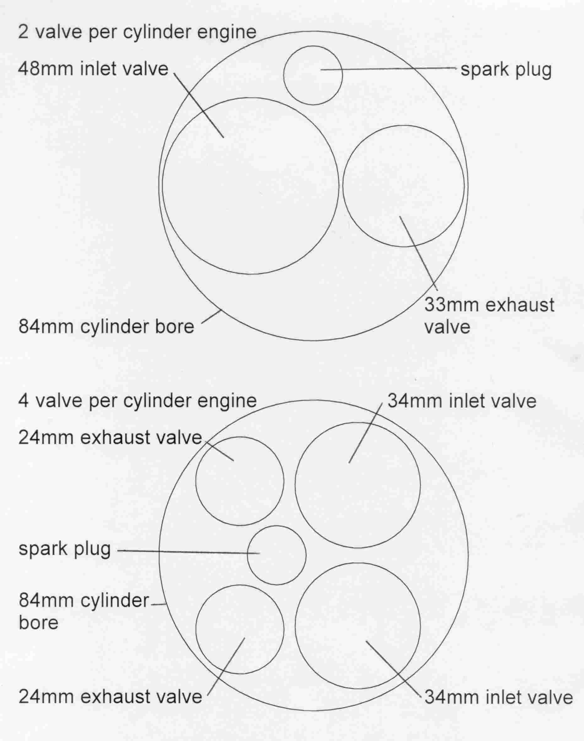
The concept of increasing valve size and / or lift to increase the area through which the air can flow is simple. As the area can be calculated for a given valve size as pi X valve head diameter X amount of valve lift, for a 38mm valve that lifts 10mm we can see that the effective area that the air can pass through is 3.14159 (pi) X 38 X 10 = 1193.8 square mm If you make that valve 44 mm in diameter, then 3.14159 X 44 X 10 = 1382.3 square mm So for a 16% increase in diameter of the valve, you actually get 16% extra area for the same amount of lift, which is a directly linear relationship. If you look at valve lift in isolation, again it can easily be calculated how much an effect an increase has. Taking the same 38mm valve at 10 mm lift, the above calculation shows the area to be 1093.8 square mm. Now if we increase lift by 10% to 11 mm, we get 3.14159 X 38 X 11 = 1313 square mm So again, for a 10% increase in valve lift, you get a 10% increase in area, again a directly linear relationship. Given these improvements, why don't we make the valves as big as possible, and lift them halfway down the cylinder? Unfortunately, with the former there is a physical limit to the diameter of the valve, and with the latter, there is the law of diminishing returns to deal with. The problem with increasing valve head size is the that the diameter of the cylinder will eventually become the limiting factor. Even if you you could make the inlet valve as large as the cylinder diameter (and you wouldn't because then where would you put the exhaust valve.....?) it wouldn't work very well because then the edge of the valve would be too close to the cylinder wall, and the little gap left would be less that a small valve. As mentioned, you also need an exhaust valve, and realistically that valve needs to be around 70% of the diameter of the inlet valve in order to not become restrictive. So that means that the inlet valve can realistically never be more than about 58% of the diameter of the cylinder. Doing the sums, taking a 1500cc boxer engine bore of 84mm, that means that the largest inlet valve can be 84mm X 58% = 48.72mm, or more realistically 48mm The exhaust valve has to be approximately 70% of this, so 48mm X 70% = 33.6mm, or more realistically 33mm The total dimension across the two valves is therefore 81mm, which will fit into the cylinder. Remember that the two valve heads cannot touch, so you have to separate them by 1mm, so now that dimension goes up to 82mm, leaving 1mm between each valve and the cylinder walls. If we assume a lift of 10 mm, that then gives us and area of 3.14159 X 48 X 10 = 1508 square mm So for a practical maximum lift of 10mm, the largest valve area we can get is 1508 square mm. But now consider the shape of the cylinder. It is circular, and two valves, side by side waste an awful amount of the area available. What if you tried to make use of that space by putting in an extra valve? In fact, it is obvious that four smaller valves can be put in. But if the valves are smaller, wont they be more restrictive? We can calculate the effect. Lets say we put in two 34mm diameter inlet valves, which if we apply the 70% rule says that the exhaust valves will be 24mm diameter. By offsetting the spark plug a little, these four valves go in very easily, not coming within 2 mm of anything else. So then if we assume a lift of 10 mm, we calculate the inlet valve area as 3.14159 X 34 X 10 = 1068 square mm per valve As there are two inlet valves, that means for a lift of 10mm, we have 2136 square mm, which is almost 42% more than the possible area with one inlet valve. That is a massive increase. That is why the four valve per cylinder engines, better known as the 16v, produce more power. There are some downsides to this. Due to the large valve area, at low speeds the air speeds at the valve throat can be quite low, which means that 16v engines lack some of the low down torque of the 8v engines. One factor that helps compensate for this in the production Alfa Boxer 16v is the use of fuel injection. Refer to the fuel system section to get more information. The practical result of all this is that though the 16v sacrifices some low down torque compared to the 8v engine, at mid range speeds, the 16v overtakes the 8v and starts to produce considerably more power, and at the top end leaves the 8v for dead. The 16v engine can be be fitted in place of an 8v engine in most applications. I have fitted the 16v in my AlfaSud Sprint. If you are interested in how this was done, go to my site Having said that, if you are wanting to modify your 16v for more power, the principles of all the above modifications can be applied more or less directly to the 16v. There is no magic involved, the 16v is just another engine after all. If you are considering this, some worthwhile points to remember are: The engine is fitted with a fuel injection system which will have to be adjusted to suit the modifications. A cam swap for a 16v is actually swapping four cams, not two. The 16v lifters are hydraulic. The valve stems of the 16v are quite thin already, I would not thin them any more. |