|
Some details of the conversion
Hopefully these images will help you see how it all went together. Or perhaps didn't, sometimes...
|
|
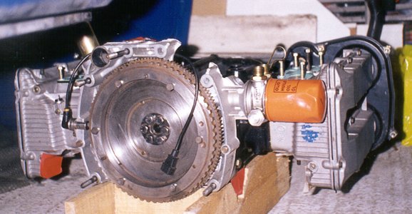
Fig 1 : The rear of the new engine. Note the crank position sensor, modified flywheel and (just visible) modified sump for oil return from heads
|
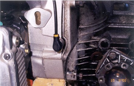
fig 2 : This is where the crank sensor exits the bellhousing to crankcase flange; note the relief on the gearbox to acommodate this. Also worth a mention is the drive shaft attachment flange on the gearbox output shaft; note there is no place for the brake discs to go
|
|
|
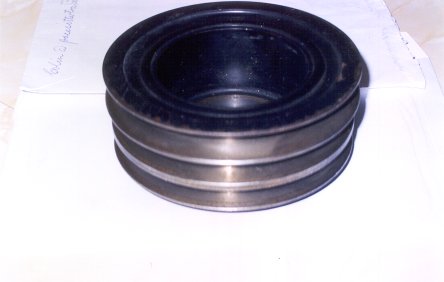
fig 4 : The unmodified original crank pulley, note the three separate grooves
|
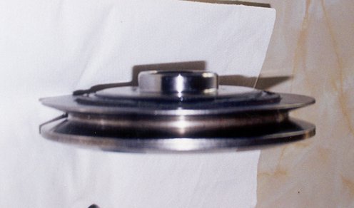
fig 5 : the modified crank pulley, only the rear pulley remains
|
|
|
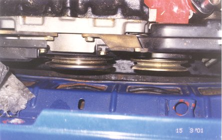
fig 7 : Note the proximity of the crank pulley to the front valance, and the where the radiator sits. One of the radiator mountings is at the bottom right of the picture
|
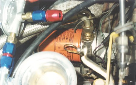
fig 8 : the oil cooler thermostat sandwich plate can be seen between the block and the filter; the adjustable fuel pressure regulator is up and to the leftp
|
|
|
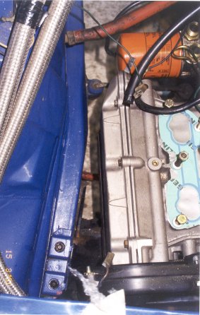
fig 10 : view of the right hand head in position; there is ample clearance between the chassis rail and the head. The two braided lines to the left are the oil cooler lines
|
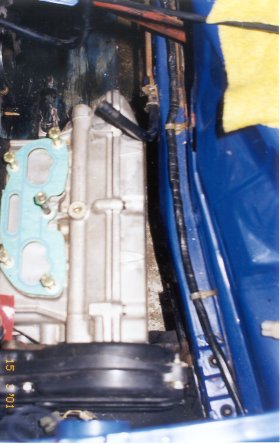
fig 11 : left hand engine block in situ. Note the very different flange pattern for the 16v inlet manifolds
|
|
|
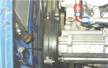
fig 13 : radiator bottom hose inlet and the water distribution block outlet; the black cam wheel cover in the centre prevents the standard 8v bottom hose from being used
|
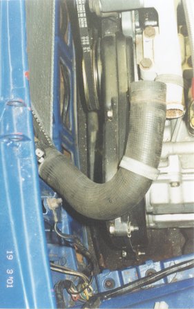
fig 14 : the cam cover pushes the hose upwards and away from the distribution block. A two part hose with a "U" shaped link pipe will be fabricated to get round this
|
|
|
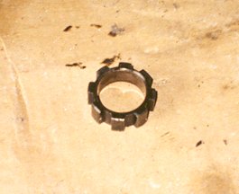
fig 16 : the electronic speedo drive phonic wheel. This must be replaced with the conventional speedo drive worm gear if you are to keep the Sud / Sprint mechanical speedo
|
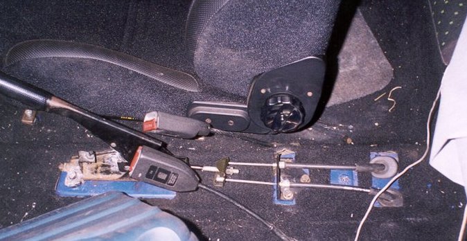
fig 17 : the 33 handbrake assembly in place - please disregard the dirty carpet!
|
|
|
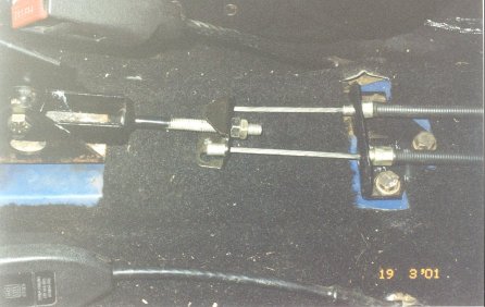
fig 19 : the handbrake adjuster and triangular bracket; note that the late Sprint carpet was pre-cut to accept these items. Remember to get all these items from your donor car
|
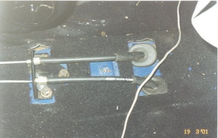
fig 20 : the oval holes for the cables and the three threaded holes for the triangular bracket were already there, as were the cut outs in the carpet. The two oval gromitts will have to be taken from the donor car
|
|
|
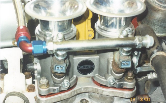
Fig.23 Fuel Rails
|
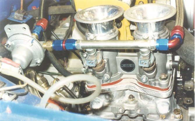
Fig.24 Jenvey Throttle Bodies
|
|
|
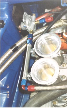
fig 25 : another view of right hand side of the engine; note the proximity of the radiator top hose to the throttle body
|
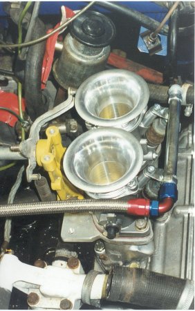
fig 26 : Left hand side of engine; note the twin carburettor linkage cross-shaft
|
|
|
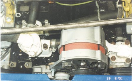
fig 28 : centre of engine - not much to distiguish it from an 8v installation, though the alternator will need shims to move it forward slightly
|
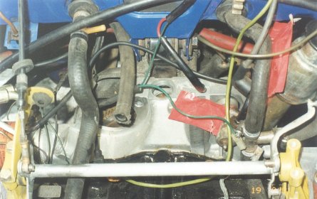
fig 27 : rear of engine, again very little different to the 8v; cross-shaft is slightly shorter than carb application. Note hole for mechanical distributor, and starter position
|
|