|
|
|
Fuel System
The fuel systems fitted to Alfa Boxers changed considerably during its life. Only two of these are really worth mentioning here, that is the twin IDF/DRLA carburettor setup and the fuel injection systems. If the car you have is carburetted, it is obvious that the first step you should take is to make sure that you have the twin Weber IDF or Dell'Orto DRLA carburettors and manifolds fitted. You then can decide what to do from there, from modifying your carburettors, to fitting larger ones, to fitting aftermarket injection. If your car is injected, your choices are a little more difficult. You can change to aftermarket injection, but it will not be very cheap, despite the fact that a lot of the hardware is already fitted to your car. Alternatively, if you perform the modifications to the cylinder heads etc, then your existing injection will have to be adjusted to suit the mods. I am not even going to attempt to deal with that, but there are many aftermarket tuners who have relatively simple ways of doing this. All the engine tuning mods will work with injection with suitable adjustments, and in fact may work even better than with the carbs.
What do we want from the fuel system?
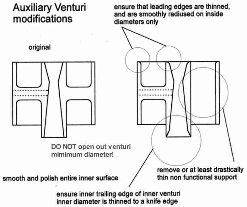
In order to get the best from the fuel system, an understanding of what it does is important. General Principle In its simplest form, whether it is carbs or injection, the fuel system is a device that adds fuel to the air being pulled into the cylinder in the correct way and in the correct quantities. The correct way means that the fuel must be distributed in the way that makes the air and fuel mix burn best. This requires that the fuel is finely atomised, like a spray. The correct quantity of fuel is that that produces the best power or emissions for any given quantity of air. The problem is that you need to achieve these conditions at a wide variety of rpm, and at different power levels, and constantly changing conditions. The best power is achieved at a certain, rich air to fuel ratio. The best economy and emissions are achieved at a different, leaner air to fuel ratio. When an engine is cold, it needs more fuel to achieve combustion. As you accelerate, a slightly richer mix is needed. When the air is hot, or the engine is at altitude, less fuel is needed. In every case, the fuel and air must be mixed well enough to ensure that all the fuel is burned fully. It can be seen from this that the first factor that we need to compensate for is the amount of air being inducted into the engine. Whatever is being used has to calculate the air being drawn in then add the precise quantities of fuel needed. But how can you measure air? Air, like all things, has certain physical properties. Air actually behaves like a fluid, and we can use some of these properties to help us. When air is still, it has a certain pressure it exerts on things around it. As air speeds up, it loses pressure, and so a local partial vacuum forms. This is what happens with an aircraft wing, and the lower pressure of the air rushing over the top curved surface sucks the wing upwards. This is the effect that a guy called Bernoulli noticed, from which we get Bernoulli's theorem. So if you have a tube, and that tube has a narrow point in it, if you push air through the tube, the air has to squeeze up to get though the narrow part. As it squeezes up, it speeds up, and that means the pressure drops at that point. If you then measure that pressure drop, you will see that if the air speeds up further, the pressure drops further in proportion. Than means that we have a crude way of measuring the air going through the tube. A carburettor uses this principle, with the air passing through a restriction, called a venturi, or more commonly a choke. The fuel is fed to this middle restriction by a tube, from a little reservoir in the middle of the carb. The reservoir is always kept at a certain level, just below the level of the transfer tube. As the air rushes past the venturi, it sucks fuel from the reservoir. The more air that is pulled into the engine, the faster the air that rushes past the venturi, and the harder it sucks fuel in. In order to make sure that the correct amount of fuel is being sucked in, it is controlled by a calibrated hole, called a jet. The size of that hole can be changed to richen or weaken the mixture. This is a basic carburettor. Obviously, a real carburettor is more complicated than this. This is due to the fact that the engine is constantly accelerating or decelerating, or runs at very low speeds, or is cold. Low Speed Running Slow running brings a problem due to the fact that the airspeed is so low due to a low demand of air. In these conditions, the 'suck' being applied to the fuel is too low to accurately meter any fuel. What is needed is a way to amplify the suck generated, and this is done using an even smaller venturi, the auxiliary venturi. This is a little tube with its own tiny little venturi which sits in the middle of the main venturi. The fuel is fed to the middle of this, and as it accelerates the air even more, it generates a suck at low airflow rates. But in certain very low speed conditions, even this is insufficient to provide the airspeed necessary for the suck, or signal. At idle, virtually no air is flowing through the carb. There is no signal generated at the auxiliary venturi either, so we need to look at another way of metering fuel into the engine. The carburettors are fitted with an airflow control device, the butterfly valves. Closing this stops the engine receiving air, and therefore slows the engine. When the butterfly is closed, the engine is still trying to pull the air in, and a massive vacuum forms between the carb butterfly valve and the inlet valve. If the butterfly is closed completely, insufficient air gets to the engine and it stops, so there must be a way of getting just enough air to the engine to let it idle. You can do this in one of two ways. Either open the butterfly valve slightly, or provide a little drilled hole behind the butterfly valve to let a little air through. This only provides air, though. But in each case, the air is being pulled through these gaps or holes quite quickly, so if we make a miniature version of the main fuel system, we effectively make a little carburettor just for idle speeds. As the idle speed is constant, it can be a very simple setup. In addition, by putting additional little fuel feed holes further up the carburettor, just by the tip of the butterfly valve, as the throttle is opened slightly you can progressively increase the fuel until the main fuel circuit comes into play. These are the idle circuit and progression circuits respectively. Cold Starting The engine also needs to be able to give the engine more fuel when it is cold. To deal with this is a fuel jet that has a needle sticking through it. The needle is moved in and out by a mechanical lever attached to the outside of the carburettor. When the needle is pulled out, a large hole is presented, and lots of fuel can flow into the carburettor, richening the mix. Once less fuel is needed, the needle is pushed back in, progressively blocking off the flow of fuel, until when fully closed no fuel is flowing. This is the cold start enrichment device.If you look at this, you will see that effectively one carburettor is made up from three sub-carburettors, the main circuit, the idle and progression circuit and the cold mixture enrichment circuit. Each has its own jets, and each is independently adjustable. Acceleration Unfortunately, there are further complications to this. Consider the engine running at a steady speed. The main circuit is feeding fuel at a certain flow rate. If you snap open the throttle, suddenly you are allowing much more air into the engine, and you instantly need more fuel to match that air. The fuel flow through the main circuit cannot accelerate as fast as the air can, so the effect is that the engine is momentarily fed with a mixture that is far too lean. The lean mix does not burn that well and also very slowly, and so you get a big hesitation, accompanied by a cough. Very often a spit back of flame through the carb occurs as well, as the mixture burns so slowly that it is still burning when the valve opens next, igniting the fresh charge of fuel and air.To overcome this, a means of instantly injecting some fuel into the engine when the throttle is opened quickly is needed. The carb therefore employs an accelerator pump, which is linked by a spring to the butterflies. As the butterflies open, the spring is compressed, which then pushes against a little piston, which pushes a set quantity of fuel into the acceleration enrichment jets. If you accelerate slowly, you do not need this enrichment. To compensate for this, just before this jet there is a spill valve, which returns fuel to the reservoir at a set rate. If the throttle is opened slowly, much of the fuel gets pushed back to the reservoir, preventing over-enrichment. Mixture Presentation The problems facing carburettors do not end there. Mixture presentation is important. As mentioned above, it is not enough to have the fuel and air supplied in the correct ratios, you must also ensure that they are finely mixed. Large drops of fuel burn slowly and inefficiently. Not only that, but they are heavy, and unless the airspeed is high enough, they can drop out of the airstream, and coat the walls of the manifold and inlet tract. You have to add more fuel to compensate for this, so economy and efficiency suffers.The carburettor tries to overcome this problem by pre-mixing the fuel with air, to form what is called a fuel air emulsion. This is in fact what is fed to the main fuel circuits, not pure fuel. The fuel is mixed with air in the emulsion tubes, using air drawn in through the air corrector jets. This emulsion is then much easier to break into tiny droplets that a steady solid stream of fuel. Some idle circuits also employ emulsion tubes in the form of air idle corrector jets. Float Chamber The fuel in the carburettor that feeds all these jets and tubes has to be kept at a specific height. This is so that too being too high doesn't cause fuel to run into the engine due to gravity, and too little is sucked in due to the level being too low, so the signal is sucking against gravity. The level is maintained at a predetermined level by a needle valve connected to a float. The level gets too high, the needle valve is closed, stopping fuel getting in. The level drops too low, the needle valve opens, letting fuel in.When you consider all the above, it is amazing that the carbs do as good a job as they do. Incredibly, they do this while being shaken, heated, accelerated and decelerated both back to front and side to side. They even are to a degree self compensating for air temperature, air pressure, air density, nad for minor changes to the engines. But, a carburettor, at it's best, is a compromise. If you make it small enough to make sure that you get good low down power and economy, it is restrictive for top end power. Make it big enough for good top end power, and you cannot accurately control the low rpm fuelling, so economy and driveability suffers. In an attempt to get the best of both worlds, twin choke progressive carburettors were made, which are effectively a small carburettor joined to a big one. At low throttle openings and rpm the small carburettor does all the work, but as the throttle is pushed further open, the bigger carburettor joins in the action. These work quite well. The trouble is that we want power with a capital 'P'. That means that we want the biggest carburettors possible to make sure we don't waste one bhp. Well, by going from 36IDF's to 45IDF's you probably will gain, say, 2or 3 bhp. That will be a gain in peak power, say at 5,800 rpm. Unfortunately, at 3,000 rpm you have just lost 15, maybe 20 bhp. In fact, until your engine is revving at 4800 rpm, you have lost power. You are prepared to live with that to get more peak bhp? Ok, try this. Get a friend to sit next to you, and then take a good drive down some lanes. Make sure that he watches the rev counter, and get him to try and estimate the amount of time you actually spend driving with the rpm at higher than 4500. Unless you are on a race track, it is a pitifully small percentage of the time. In fact, in town and in traffic, it is doubtful that you'll get up to 4500, let alone over it. The fact is that the vast majority of your driving is done on
part throttle at medium to low revs. Most of the time it will be the idle and progression
circuits that are fuelling your car, not the main circuit. It stands to reason then, that
the smallest carburettor that can flow the amount of air your engine needs is the best
carb for you. Carburettors
The Weber IDF and Dell'Orto DRLA carburettors are basically the same functionally, but their components are not interchangeable. Some people prefer the Webers, some say the Dell'Orto's are better. I cannot detect the difference between the two driving them, but if I had to recommend which to use, I would have to suggest the Webers. They are much more common, and in my experience you are much more likely to get a rolling road that works as a Weber agent than a Dell'Orto one. Whatever, the mods that can be done will apply to both anyway. The 36DRLA's, 36IDF and 40IDF carbs were all fitted to boxers, the 40's only being fitted to the later 1.7's. For a mildly modified 1.5, the 36's are perfectly adequate, and even preferable, as they give better torque at low speeds and better economy and emissions. For highly modified 1.5's and any 1.7's, the 40's make sense. The general rule of thumb for me is that if there are two carbs that flow the same amount of air, the smaller carb is the one to go for. This is due to the higher airspeed through the carb giving a better signal and therefore a more accurate metering of the fuel and better atomisation. This is what gives the better torque at low speeds. Some small modifications can be made to the carbs in order to get the best out of them. If you could get the 36's to flow as much air as the 40's, you would get the benefits of both carbs. You can go some way to achieving this by eliminating all the restrictions in the carb, but you must do so without making the venturi (choke) larger. Some may argue that the venturi is the largest restriction in the carb, but in practice, it appears that there are other parts that affect flow. By subtle modifications to the butterfly spindle and retaining screws, smoothing and polishing the auxiliary venturis and the main choke, and making sure that there are no sharp edges or die marks on the bores of the carbs, they can be made to flow better. In addition, making sure that the air can easily get into the carbs helps, which is why all sports cars have those great looking ram pipes on the carbs.
Fuel System Alternatives
Quite obviously, it can be seen that fitting a later 1.7 injected engine ( apart from a 16v - see further on) into a non injected car means one of two things; either you convert the engine to carburettors, or you convert the car to accept the Alfa original equipment injection system. Another option is available, and that is to set the engine up so that it can accept either carbs or aftermarket fuel injection. More on that later. Option 1 is to fit carburettors to the engine. To do this will involve the carburettor intake manifolds and the twin carburettor linkage to work with them. Should you find that you cannot fit the mechanical distributor driven pump, you will also have to fit an aftermarket electrical fuel pump capable of delivering sufficient fuel to the carburettors, and fit the necessary wiring for that. The injection inlet manifold and the twin carburettor manifold have almost the same head mating flange pattern, so at worst some small modifications will have to be performed to them. The carburettors will allow the engine to run, even if they were from a 1300 or 1500, but you will have to re-jet them to get the best from them. The advantage of this method is that you can keep your carburettors (and if you have them, aftermarket filters), reuse your throttle linkage, existing fuel lines, it is simple, and most rolling roads can sort out your jetting and setup. In countries where homologation of cars is taken to an extreme, the standard appearance will cause less problems. The disadvantage is the fact that carburettors will not make the best of the engine in terms of smoothness or driveability. You will to re-jet your carburettors and settings, but despite this the carbs will never match injection for smoothness and low down torque, and well set up the injection could give better power, using less fuel to do it. Carbs will give you a headache at Mot emissions time, too.
Option 3 is to use the carburettor manifolds with an
aftermarket injection system. This means that although you have to fit the high pressure
fuel plumbing and pumps, the injection hardware is a straightforward swap with the
carburettors, and the wiring in of the injection electronics, while not a ten minute job,
is not that tricky. 16V engine fuel systems for a transplant
Option 4. Use the 16v throttle bodies, with an aftermarket electronics setup like the M3D or Weber Alpha systems. Aftermarket Injection Systems The OEM throttle bodies used on the standard 16v engine are simple Dell'Orto manufactured 40mm diameter butterfly items which are integral with the inlet manifold and bolt straight to the head. They are a neat setup, and quite nicely made. One of them has a 'D' ended shaft onto which is fitted a throttle potentiometer, and there is a sturdy and simple cross shaft throttle linkage that links the two bodies, in a similar way to the carburetted engines. The filter housing and mass flow sensor are an integrally cast unit that has four individual long runners to each cylinder, sleeved over the outside of the top of the throttle bodies. Virtually all this can be used, if so desired, as it is well executed, and the long runners combined with the (relatively) small 40mm throttles will aid torque. If you are in countries that are tough on homologation issues, it may be essential that you use them. By simply hooking up the engine sensors, injectors and throttle potentiometer to an aftermaket system, You can gain many of the advantages that a programmable setup brings. The 16v (and many of the injected 8v engines) have a flywheel 60 -2 toothed wheel that triggers a hall effect crank position and speed sensor, so that can also be used to replace the distributor. The only real problem with the standard throttle
bodies is that it is a limiting factor in how far you take the engine tuning. For getting
the best torque, the standard items are pretty good. For higher states of tune (cam
changes, bigger valves, serious head work or overboring or stroking), the 40mm throttles
become restrictive to ultimate power. To get around that problem, it is necessary to
employ larger diameter throttle bodies. Physically fitting the Injection hardware, and setting up
Jenvey 45TF throttle bodies
You will see from the photos that it all
fits neatly. I had the manifolds modified by Alfa II, which, as stated above, involves a
fair amount of work. I did do a little work on them myself before the definitive
installation, to allow some clearance for the throttle linkage, plus some minor dressing
just to make them look pretty. This is not to say that the work done is in any way bad, it
is just that I did a couple of cosmetic improvements that took a while to do, but I am
certain that you wouldn’t want to pay someone to do it. Whatever, part of doing
something like this is to see a nicely presented engine and all the little details give it
a more professional look, which you can be proud of. I had previously had some doubts
concerning the routing of the return line. The non injection tank fitted to my car is not
rusty (a miracle) so I wanted to keep it if at all possible. The trouble was that there
was no swirl pot in the tank, and the fuel return line was not positioned very well. Wiring in the M3D unit
Fitting the injection was not as great a problem
as I had imagined it to be.
The complete M3d package You will have to make up the loom yourself. It
sounds daunting, but anyone with a little experience of car electrics will be fine. To
what Emerald supplied, I added the following:- One of the first things to decide is whether you will be using conventional ignition or distributorless ignition. Refer to the ignition section for more details. You will then have to decide whether to go for batched or sequential injection. I went for batched, being simpler, but left the connections in place to enable an easy change at a later date. The fuel pump has to be installed, complete with a pre filter. The prefilter acts as a swirl pot as well as protecting the filter. Obviously an earth wire is needed, and the +12 volt supply wire was routed through the car to protect it. In the battery tray it was connected to a relay block that also has slots for three blade fuses. The supply wire was connected so that it was switched live by the relay when energised, and then passes through a fuse before going to the pump. The switching circuit of the relay was connected
to +12 volts on one side, and the other terminal connected to the 'fuel pump relay driver'
connection of the ECU. In this way the relay earths via a switch in the ECU. When the ECU
detects engine rotation, the switch closes, actuating the relay and energising the pump.
Should the engine stop (an accident, for example) the pump is automatically cut. The injectors are all fed with a +12 volt supply, and again are earthed through a switched connection on the ECU. As I was making a batched injector setup, it meant that I connected all four injectors in parallel, with all four positive supplies coming together and all four negative connections coming together. The injection connectors are a standard type, and use crimp on connectors. To determine which is the positive terminal of the injector, just look at the plastic body of the connector; there will be a '+' to indicate it. Also, remember to put the protective boot over the wire before pushing the crimp connectors into their housing. The positive wires are all then connected to the +12 volt switched supply, through one of the fuses on the relay block. The negative connections are then connected to the 'Injector driver' connection of the ECU. The crank sensor is a little more tricky. I would recommend that you make three individual connections for the wires, so that you can swap them around until you get the ECU to recognise the sensor signal. There are six possible combinations for connecting to the three relevant terminals of the ECU, and four of them will not work. Of the two remaining combinations, both will work, but one will be correct and the other not. however, to get you up and running, either will do, especially if you are only using the injection. The throttle potentiometer is simple, as the colours are all referred to in the instruction manual. All you have to do is cut the right length of wires, crimp the terminals on and push them into the receptacle. The air and water temperature sensors are also easy, sharing a common earth, with the remaining terminal being connected to the respective pins on the ECU. The connector type is the same as the injectors, but there is no need to get the wires to any particular terminals. The ECU requires a good quality earth. Connect this to or as near to the battery earth itself as you can. I would recommend that the loom be manufactured and installed in-situ, and that all the cable runs are sorted out there and then to ensure that you don't end up with over long, or worse still, short cables.
Getting it all working...
Once all this injection and
distributor-less ignition hardware had been fitted, I had to try to make it all work
together. I attempted to use the instructions that come with the EMS to get the engine
running. The EMS came programmed with a basic,
safe fuel and ignition map from a similar sort of engine, perhaps from a 1.6 or 1.8 ford
Zetec. The engine did not want to run using this, point blank. After many hours of trying,
I decided to take a step back and simplify the system in order to attempt to diagnose why
it wouldn't run. I had previously stated that I might run
into problems, and that as a contingency I could stick on the carbs and the distributor.
Well, that proved to be my saviour, or at least some of it did. I could not very easily
stick the carbs on because it would mean a change of fuel pump, plus devising a means of
attaching the throttle pot to the carbs. The distributor, however, could simply be bolted
back into place, and the connections remade by re-attaching the spade connectors. Refer to
the ignition section for more details. The original plan was that, since the
EMS can be reprogrammed using a laptop, I could play around to set everything to a
reasonable standard. I would then take the car down to Emerald Cams rolling road in south
London, and spend a day getting it set up perfectly. I would then drive it home with a big
happy smile on my face. The reality was that we were having
problems getting the engine to run smoothly, especially at low speeds. This, plus some
other issues (water leaks from one of the inlet manifolds and the thermostat housing, plus
some massive toe in on the front suspension) delayed getting the car onto the road in
sufficient time to take it to Emerald for mapping. What we did achieve, though, was to get
the car onto the road and start to at least find some approximate settings. Things did not
start well. For that matter, nor did the engine! It was an absolute pig to start with.
Trying to pull away from a standstill would cause the engine to bog down, even using 4000
revs. Part of that was traced to the handbrake being adjusted too tight, with one of the
shoes hanging on. This was corrected, and things improved slightly. To give you some idea, the little
cul-de-sac where we were starting from was 50 metres long, and we were starting from the
middle. It took 20 minutes of adjusting settings before we were able to make the 25 metres
to the end of the road.... Once we had the car pulling away from a
standstill ok, we started to go a bit further. This highlighted the massive toe-in that
the new suspension had endowed the car with. It simply did not want to turn. Very un-Alfa!
The toe in was improved by eye, and we could now take the car further afield. A nearby
industrial estate had some nice open roads, many of them dual carriageway, with virtually
zero traffic on it, and we headed for it. Once there, we made rapid inroads in roughly mapping the injection (no ignition yet, remember) and it got to be good enough that we headed for a garage to get the tracking done properly. However, by this time we had missed the chance to take the car to Emerald Cams for mapping. Such is life..... A couple of problems surfaced during the rough setting up that we were doing. Firstly, it became clear that the fuel pressure was way too low for the map that we had intended staring up with. As a result we had to massively richen the fuel sites at the bottom end just to make it all work. The resulting fuel map looks like a complete disaster area because of this, but it does enable the car to run. Secondly, as mentioned in the ignition section, speed site 1 is non-existent due to the crank sensor output dropping below the threshold that the ECU can read, so the ECU hunts between speed site 0 and 2 at idle. Whenever the speed site is 0, the fuel pump is switched off as the ECU thinks the engine is stopped. This means that the mixture had to be richened even more to cover the dead moments when the fuel was cut. The emissions at idle were a country mile off, and a sub 1,000 rpm idle at the moment is not possible. When the car was taken for rolling road mapping, this found to be that I had wired up the sensor with two wires inverted. It was clear that without some diagnostic equipment to help, just looking at one aspect of the fuel and ignition system at a time was the way to go. When the engine didn't want to start, it was not possible to determine whether the fuel or the ignition was wrong, so substituting one of those with a known quantity allows you to concentrate on getting one parameter correct. You can then go back and correct the other one. Once we actually got the engine running, it was a (relatively) short time between then and having the car in a condition where it could be driven reasonably well. It was an enormous sense of achievement, too. Once the car was at the rolling road, the problems were sorted one by one, and the mapping of the engine began in earnest. On leaving Emerald, it was clear that the engine was stonking.
|
|||||